AMC 20-152A
Compliance Assurance for Simple COTS Devices
How DO-254 and AMC 20-152A treat simple COTS devices, which objectives apply, and which assurance activities remain prudent in an airborne electronic hardware programme.
- Author
- AeroDAS Engineering Team
- Reviewed by
- AeroDAS Technical Review
- Published
- Last reviewed
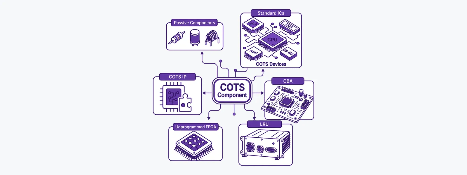
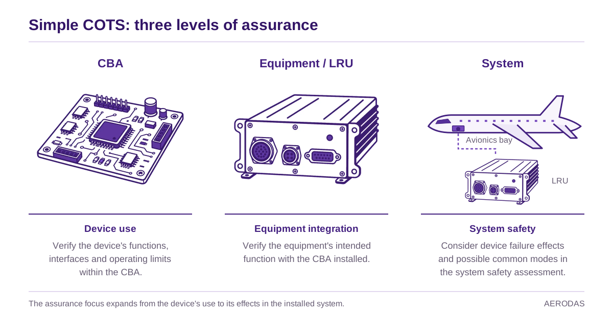
COTS terminology spans several levels of integration. AMC 20-152A Section 6 uses “COTS device” for a fully encapsulated semiconductor product—not for a complete CBA or LRU.
Commercial off-the-shelf (COTS) devices are everywhere in airborne electronic hardware (AEH): voltage supervisors, ADCs, temperature sensors, CAN controllers, memories and microcontrollers. Yet one apparently simple question can create disproportionate debate during certification:
What compliance assurance is expected when a COTS device is classified as simple?
The short answer is easy to miss. AMC 20-152A requires the applicant to assess and document the COTS complexity classification through Objective COTS-1. However, the development-assurance objectives in Section 6.4 are written for complex COTS devices. A device classified as simple is therefore not automatically subject to the full COTS-2 through COTS-8 objective set.
COTS-1 establishes and records the classification. For a simple COTS device, the Section 6.4 objectives do not automatically apply; any additional activities depend on its intended use.
That does not mean “do nothing.” It means separating three different layers:
- the activity required to justify the classification;
- the assurance already provided through board, equipment and system processes; and
- additional good practices that may be adopted because of the device's use, risk or certification context.
Simple means comprehensively verifiable—not merely small
DO-254 introduces the distinction between simple and complex hardware. In practical terms, simplicity depends on whether a comprehensive and deterministic combination of tests and analyses can demonstrate correct performance for every foreseeable operating condition, without anomalous behaviour.
AMC 20-152A makes an important refinement:
| Item type | Classification guidance | Main focus |
|---|---|---|
| Custom device | Section 5.2 | Design content and the ability to verify the applicant's own design comprehensively |
| COTS device | Section 6.3 | Internal interaction, modes, configurability, resource sharing and advanced processing |
The custom-device criteria should not simply be copied onto a COTS assessment. For COTS devices, Section 6.3 defines a device as complex when it has interacting functional elements, a significant number of modes and configurable data flows or resource sharing—or when it includes advanced processing, advanced switching or multiple processing elements.
The assessment must consider all device functions, including functions intended to remain unused. An unused DMA engine, hidden bus master or configurable interconnect can still affect the classification because it may interact with resources used by the airborne function.
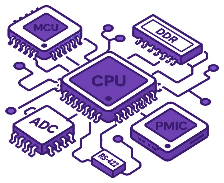
This is why component size, pin count and marketing labels are weak indicators. A physically small device can be complex, while a comparatively capable device may still be simple if its architecture and behaviour remain bounded and comprehensively verifiable.
What AMC 20-152A actually requires
Three statements establish the scope:
- Section 6 says its objectives support compliance when using complex COTS devices.
- Section 6.2 states that Section 6.4 applies only to devices determined to be complex.
- Section 6.4 explains that its objectives supplement ED-80/DO-254 Section 11.2 for certification credit involving complex COTS devices.
Objective COTS-1 still matters. The applicant should assess relevant COTS devices using the Section 6.3 criteria and record the relevant devices and rationale in the PHAC or a related planning document. AMC 20-152A does not expect a written assessment for every resistor or every line item in the bill of materials. It focuses attention on devices relevant to the classification decision—especially devices that are clearly complex or near the simple/complex boundary.
The objective scope after classification can be summarised as follows:
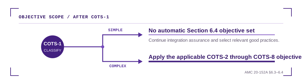
The EASA CRD to NPA 2018-09 removes much of the ambiguity. In its response to Comment 190, EASA stated that no activities are required for simple COTS devices. Read in context, this means no additional Section 6.4 activities are triggered merely by the simple classification. It does not remove COTS-1, normal component management controls, requirements based board verification, environmental qualification, system safety assessment or configuration control.
Why CM-SWCEH-001 still appears in company procedures
Before AMC 20-152A, EASA CM-SWCEH-001 provided a broader framework covering simple, complex and highly complex COTS devices, as well as custom devices and problem-report considerations. Organisations that built their procedures around the memorandum may therefore expect a named assurance activity for simple COTS devices.
Today, the memorandum is legacy material. EASA's document page marks CM-SWCEH-001 as “Superseded” by ED Decision 2020/010/R. It can be useful as historical or supporting literature, but it should not be presented as the current EASA acceptance standard. AMC 20-152A now provides the principal AEH development-assurance framework.
The transition created the apparent “gap”: AMC 20-152A contains detailed Section 6.4 objectives for complex COTS devices, but no equivalent mandatory objective set dedicated solely to simple COTS devices. That is a deliberate scope choice, not evidence that the device can be ignored.
Good practices for a simple COTS device
FAA AC 00-72 identifies several useful practices for simple COTS devices. Their applicability depends on how the device is used.
| Topic | AMC objective associated with complex COTS | Sensible treatment for simple COTS |
|---|---|---|
| Complexity classification | COTS-1 | Required for relevant devices; document boundary cases and the rationale |
| Component management | COTS-2 | Not automatically imposed by Section 6.4, but normal ECMP controls should still identify the exact part, data, qualification status and changes |
| Use outside datasheet limits | COTS-3 | Uprating is considered best practice when a simple device is used outside specified values |
| Errata | COTS-5 | Assessing relevant errata and verifying mitigations is considered best practice |
| Failure effects and common modes | COTS-6 | Considered best practice when the simple device interfaces with software |
These practices should be selected according to the device's intended use and the associated risks. They do not automatically make COTS-2, COTS-3, COTS-5 and COTS-6 applicable to every simple COTS device.
1. Keep the component under practical configuration control
Even without invoking COTS-2 formally, the project should know what it is certifying. A compact record can include:
- manufacturer and complete orderable part number;
- package, grade, mask or revision information when available;
- datasheet and user-manual revision;
- applicable errata revision;
- procurement and counterfeit-avoidance controls;
- change-notification and obsolescence arrangements; and
- the functions used, unused or disabled in the installation.
This evidence is often already produced by the organisation's electronic component management process and CBA development process. Reuse it instead of creating a parallel “simple COTS” life cycle.
2. Treat operation outside the datasheet as a new assurance problem
Suppose a temperature sensor is rated from −40°C to +85°C, but analysis predicts a local cold-soak temperature of −45°C. Its simple classification does not make the five-degree excursion acceptable. The applicant now needs substantiated evidence that the device remains technically suitable and reliable in the expanded range.
AC 00-72 describes an uprating process as good practice for this situation. The evidence may need to address production variation, lots or dies, ageing and the relevant electrical or timing characteristics—not only a one-off bench test on a single sample. Equipment level DO-160 testing is not automatically a substitute for characterising the component outside its guaranteed limits.
3. Assess errata throughout the product life cycle
Consider a simple SPI ADC whose errata states that the first conversion after a mode change may be invalid. A credible assessment would:
- determine whether the affected mode change occurs in the intended use;
- define the mitigation, such as discarding the first sample;
- capture that behaviour in a hardware, software or system requirement;
- verify the mitigation; and
- retain the assessment so that future errata revisions can be evaluated consistently.
This is proportionate work with high value. Device simplicity does not prevent a manufacturer design error from affecting the aircraft function.
4. Feed failure effects to system safety when software is involved
For a software-accessible temperature sensor, the useful question is not “Which transistor could fail?” It is “What can the used function present at the interface?” Examples include:
- a stale value within the expected range;
- an out of range value;
- corrupted serial data;
- failure to respond;
- an unexpected interrupt; or
- a common failure affecting multiple readings or channels.
Those effects can be passed to the system safety process. Mitigation may then be allocated to software, PLD logic, hardware or the system architecture.
AC 00-72 considers COTS-6 good practice when a simple COTS device interfaces with software. The key is the interface and mitigation opportunity; the text should not be read as requiring software merely to make a simple device acceptable.
A proportionate evidence package
For many simple devices, the evidence can remain short. A practical “simple COTS record” may contain:
| Evidence item | Typical content |
|---|---|
| Identification | Exact part, manufacturer, package and controlled source data |
| Classification | Section 6.3 assessment, including unused functions and boundary rationale |
| Intended use | Used modes, interfaces, configuration, limits and disabled features |
| Verification reference | CBA/equipment requirements and tests demonstrating the intended function |
| Datasheet compliance | Voltage, temperature, timing, loading and other operating margins |
| Errata assessment | Applicability, mitigation, requirement allocation and verification evidence |
| Safety interface | Observable failure effects and common-mode considerations where appropriate |
| Life cycle monitoring | Supplier changes, new errata, obsolescence and problem-report triggers |
Case Study: A Digital Temperature Sensor
Assume a single-function SPI temperature sensor contributes to a DAL B monitoring function. It has one conversion path, one serial interface, a small fixed register set and no autonomous bus mastering.
The project could make the following argument:
- The device does not contain advanced processing, switching or multiple processing elements.
- Its limited functions do not create significant interacting elements or configurable resource sharing.
- All relevant modes and interface behaviour can be exercised deterministically.
- Unused alert features are identified and their state is controlled.
- The device is therefore classified as simple, with the rationale recorded under COTS-1.
- Section 6.4 is not automatically applied as a mandatory objective set.
- The part remains inside its published voltage and temperature ranges.
- Errata are assessed as good practice.
- Because software reads the device, interface failure effects are supplied to the safety process and the selected software monitoring is verified.
This is stronger than either extreme: applying the entire complex COTS framework without tailoring, or declaring the component simple and retaining no evidence at all.
What if the certification authority expects more?
An authority may determine that the baseline approach does not adequately address a project specific certification concern. Additional activities can then be agreed through the certification programme—for example in the PHAC, a certification review item (CRI) or another approved means-of-compliance arrangement.
Such an agreement might select elements analogous to COTS-2, COTS-3, COTS-5 or COTS-6. The selected set should be tied to the actual concern:
- COTS-2-like evidence for supply, maturity or configuration risk;
- COTS-3 when operating outside manufacturer limits;
- COTS-5 for relevant device errata; and
- COTS-6 for safety-significant failure effects, especially across a software interface.
The important point is that this becomes a tailored, project specific compliance position. It should not be described as the default wording of AMC 20-152A.
Conclusion
AMC 20-152A does not define a standalone mandatory assurance objective set for simple COTS devices. It does require the applicant to reach and document a defensible complexity classification for relevant devices. Once a device is classified as simple, assurance continues through the CBA, equipment, system safety, configuration-management and verification processes.
A sound programme therefore uses a proportionate strategy:
- justify simplicity under COTS-1;
- define the device's intended use and operating envelope;
- retain essential component and configuration data;
- assess errata;
- address uprating whenever datasheet limits are exceeded;
- communicate observable failure effects to system safety when warranted; and
- agree any additional authority expectations early in the certification programme.
The objective is not to manufacture paperwork for a simple component. It is to preserve a clear, reviewable assurance argument showing why the component is simple, why its use is controlled and why its remaining risks are adequately addressed.
Note: This article explains a general certification approach. The agreed certification basis, project specific authority position and approved plans take precedence.
“Design assurance is not only about proving that hardware works; it is about building justified confidence in how and why it works.”
Topics
- AMC 20-152A
- complexity classification
- COTS devices
- DO-254
Sources and references
- EASA, AMC 20-152A in the Easy Access Rules for AMC-20, Amendment 23, Sections 5.2, 6.2, 6.3 and 6.4
- EASA, CM-SWCEH-001 document record, marked superseded by ED Decision 2020/010/R
- EASA, CRD to NPA 2018-09, including the responses concerning simple COTS devices
- FAA, AC 00-72, Best Practices for Airborne Electronic Hardware Design Assurance, Section 3.2
- RTCA DO-254 / EUROCAE ED-80, Design Assurance Guidance for Airborne Electronic Hardware, Sections 1.6 and 11.2